8051 Microcontroller

steps to delay img

Designing a delay program using 8051 timers.

While designing delay programs in 8051, calculating the initial value that has to be loaded inot TH and TL registers forms a very important thing. Let us see how it is done.

Assume the processor is clocked by a 12MHz crystal.

That means, the timer clock input will be 12MHz/12 = 1MHz

That means, the time taken for the timer to make one increment = 1/1MHz = 1uS

For a time delay of “X” uS the timer has to make “X” increments.

2^16 = 65536 is the maximim number of counts possible for a 16 bit timer.

Let TH be the value value that has to be loaded to TH registed and TL be the value that has to be loaded to TL register.

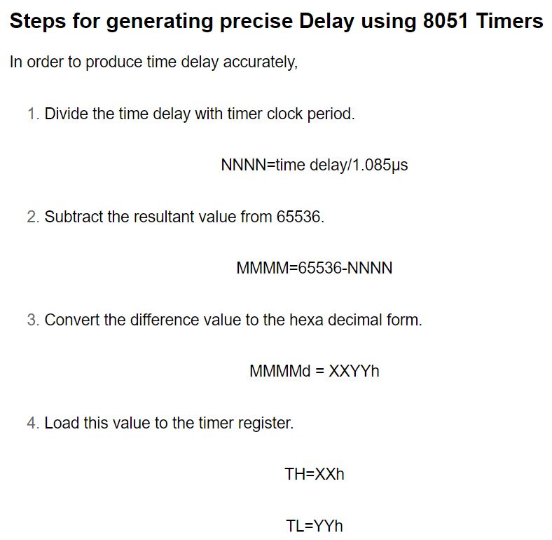
Then, THTL = XXYY( Hexadecimal equivalent of (65536-X) where (65536-X) is considered in decimal.)

Load this value to the timer register.     TH=XXh     TL=YYh


Here Time field (input) is the time period of the square wave to be generated .

If you want to create 'x' milliseconds delay then enter the value '2x' in time field for getting Count Value i.e TH and TL values


Time (in ms):

Delay (in ms):

Count Value:

CV (in hex) :


Here frequency field(input) is the frequency of the square wave to be generated using 8051 ALP

All the values of time and delay are in millisecs(ms)


Frequency not given !! No worries ..find here


Frequency(in Khz):


8051 Timers Register Description

TMOD Register

If the Count Value is 0xFFBE(say) we can use Timer mode 2 i.e 8 bit auto relaod and TH0/1=BE;


Gate C/T M1 M0 Gate C/T M1 M0
Timer 1 Timer 0

G=0 ,if we control timer/counter through software and G=1 if we control through hardware

C/T =0 , if we use timer and C/T=1 , if we use counter

M1 and M0 values are taken according to the mode of operation of timers which are given in below table .

Using above values we define the value that is to be loaded in TMOD register

EXAMPLE:

If the timer1(C/T=0) is operating in mode 1(M1=0 M0=1) ,timer0 as counter0 (C/T=1) in mode2(M1=1 M0=0) and we are controlling both timers through software(G=0) then TMOD = 16H


Gate C/T M1 M0 Gate C/T M1 M0
0 0 0 1 0 1 1 0


Mode 1 and 2 are timer modes used in 8051 microcontroller. If the Count value is less than 256 or hex value FF then the timer works in mode 2 and it is 8 bit auto relaod. If the count value is greater than 256 then the timer works in mode 1 and 16 bit .


M1 M0 MODE DESCRIPTION
0 0 Mode 0 13 bit timer
0 1 Mode 1 16 bit timer
1 0 Mode 2 8 bit auto reload
1 1 Mode 3 split timr